
What is Gear Module? Sizing and Selection Guide
Master metric gear module sizing: understand the m = d/z relationship, standard module series (ISO 54 / DIN 780), bending strength, and undercut limits.
Prepared and technically reviewed by: TORQYX Engineering Team · Methodology and team
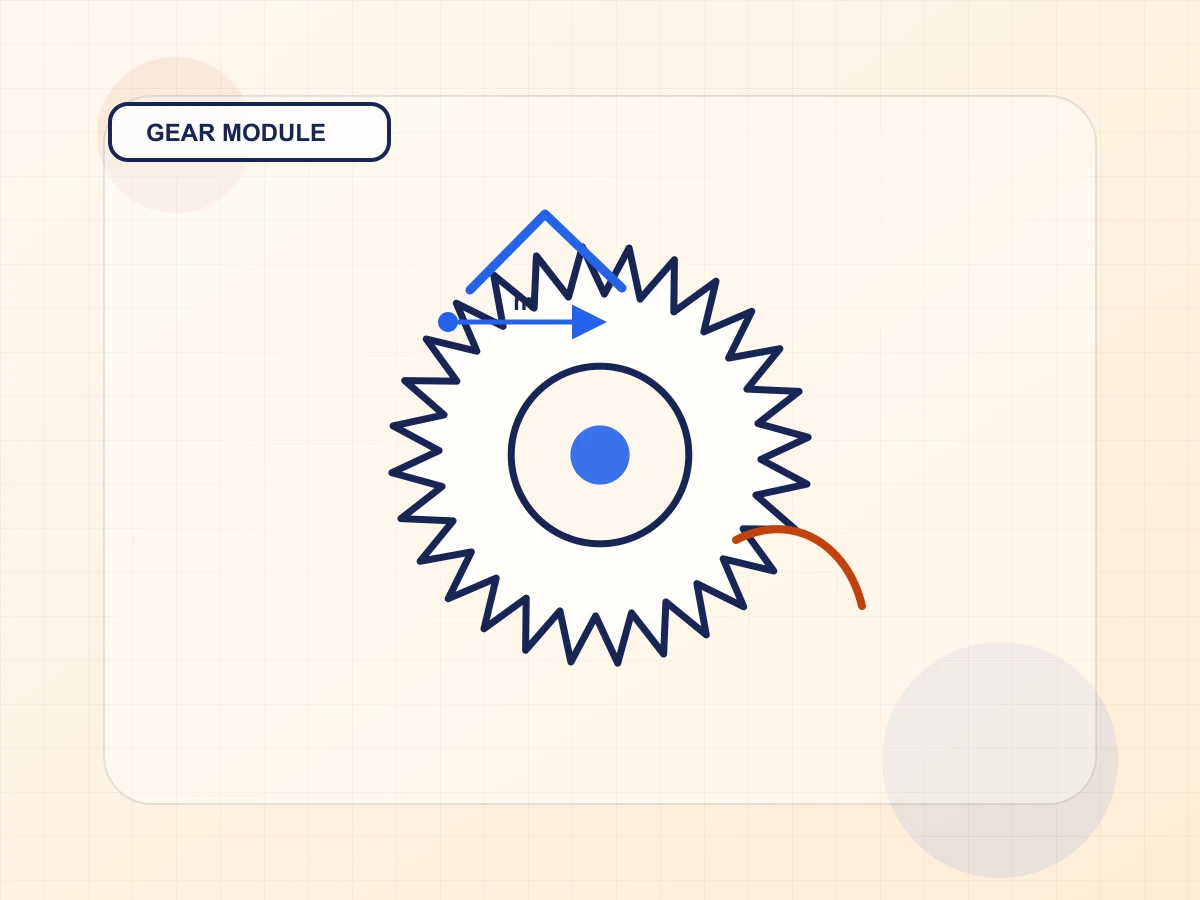
The module defines the geometric scale of a gear
In metric mechanical design, the module (m) is the foundational dimension that establishes the physical scale of gear teeth. Mathematically, it is the ratio of pitch circle diameter (d) to the number of teeth (z):
m = d / z
where:
- m is the module in millimeters (mm)
- d is the reference pitch diameter in millimeters (mm)
- z is the integer number of teeth
From the module, all other basic cylindrical gear dimensions are derived:
- Circular pitch (p): The arc distance along the reference circle between adjacent teeth: p = π · m
- Addendum (h_a): Height of tooth above the pitch circle: h_a = 1.0 · m (for standard full-depth teeth)
- Dedendum (h_f): Depth of tooth space below the pitch circle: h_f = 1.25 · m
- Total tooth depth (h): h = h_a + h_f = 2.25 · m
- Tip diameter (d_a): Outside diameter: d_a = d + 2 · m = m · (z + 2)
- Root diameter (d_f): Bottom diameter: d_f = d - 2.5 · m = m · (z - 2.5)
For two gears to mesh smoothly together in conjugate motion, they must share the identical module and identical pressure angle (standardized at 20° under ISO 53).
Raw geometric calculation vs. standardized module selection
When beginning a gearbox concept, dividing target pitch diameter by desired tooth count usually yields an arbitrary non-integer decimal (for example, m = 3.14 mm or m = 4.37 mm). However, production gears should never be manufactured with non-standard modules unless an aerospace mass-minimization constraint strictly mandates custom hobs and cutters.
Gear cutting tooling (hobs, shaper cutters, and grinding disks) is produced in standardized preferred metric series defined by ISO 54 and DIN 780:
- Series 1 (Primary preferred): 0.5, 0.6, 0.8, 1.0, 1.25, 1.5, 2.0, 2.5, 3.0, 4.0, 5.0, 6.0, 8.0, 10.0, 12.0, 16.0, 20.0 mm
- Series 2 (Secondary choice): 1.125, 1.375, 1.75, 2.25, 2.75, 3.5, 4.5, 5.5, 7.0, 9.0, 11.0, 14.0, 18.0 mm
Standardizing on Series 1 drastically reduces manufacturing lead time, inspection tooling expenses, and spare part inventory costs across the equipment lifecycle.
Core criteria for selecting an optimal module
Selecting a module is not a standalone geometric exercise; it involves balancing mechanical load capacity against acoustic noise, envelope size, and tooth kinematics:
-
Tangential force and tooth bending fatigue: Transmitted torque T produces a pitch-line tangential force: F_t = (2 · T) / d Larger modules create thicker tooth roots, resisting Lewis bending stress and cyclic fatigue under shock loads.
-
Contact stress (pitting and surface durability): While root bending strength increases linearly with module, surface contact durability (Hertzian contact pressure) is primarily governed by pitch diameter, face width, and material surface hardness (case-carburizing, nitriding, or induction hardening). Increasing module without increasing pitch diameter does not solve surface pitting issues.
-
Pinion tooth count and undercut risk: For standard 20° involute gears without profile shift, cutting teeth with a standard rack generates undercut (material removal at the dedendum root) whenever the tooth count drops below 17: z_min = 2 / sin²(α) = 2 / sin²(20°) ≈ 17.1 When designing a compact pinion with z < 17, engineers must apply a positive profile shift coefficient (x > 0) to avoid weakening the tooth root or reducing the active contact ratio.
-
Pitch line velocity and acoustic noise: At high rotational speeds (v > 10 m/s), smaller modules with larger tooth counts generate higher contact overlap ratios (contact ratio ε_α > 1.4), producing significantly lower vibration, smoother mesh transition, and quieter gearbox operation than coarse teeth.
Sizing procedure and iterative refinement
A reliable design process follows these steps:
- Determine required gear ratio and estimate initial pitch diameters based on available center distance.
- Compute raw module m_raw = d / z and round to the nearest ISO 54 preferred standard module m_std.
- Recalculate exact reference diameters d = m_std · z and center distance a = m_std · (z₁ + z₂) / 2.
- Verify root bending strength according to ISO 6336-3 and contact safety according to ISO 6336-2.
- If bending safety is insufficient, evaluate whether widening the face width b (typically b ≈ 8–12 · m for spur gears) or specifying higher grade alloy steel (such as 18CrNiMo7-6 or 42CrMo4) is preferable before unnecessarily upsizing to a larger module.
Related Torqyx calculator
Use the Torqyx Gear Module Calculator to rapidly determine raw module, standard ISO series selection, pitch dimensions, and undercut warnings.
Gear Module Calculator
CalculatorCalculate gear module, pitch diameter, circular pitch, and standard ISO module selection.
Related engineering guides
- Machine Element Life and Fatigue Sizing Guide
- Industrial Viscosity and Lubricant Classification Guide
Technical references
- ISO 54 — Cylindrical gears for general engineering and heavy engineering — Modules.
- ISO 53 — Cylindrical gears for general and heavy engineering — Standard basic rack tooth profile.
- ISO 21771 — Gears — Cylindrical involute gears and gear pairs — Concepts and geometry.
- ISO 6336-1 to 6336-5 — Calculation of load capacity of spur and helical gears.
Related posts
How to Calculate Hydraulic Cylinder Force and Speed
Calculate push and pull forces for hydraulic cylinders using pressure, bore diameter, and rod diameter. Account for mechanical efficiency and buckling safety.
The Difference Between Torque and Power: An Engineering Perspective
Understand the fundamental relationship between torque and power, P = T x omega, and how to size electric motors and gear reducers correctly.
Shaft Sizing: Torsional Stress and Angle of Twist
Pre-size a solid shaft from torque, allowable shear stress, and angle of twist. Understand why torsion is only the starting point—not the whole design.
Related calculators
Coating Guide
Summary of coating types and corrosion protection.
Fillet Weld Sizing
Find required fillet size from load, weld length, and allowable stress.
Gear Backlash
Estimate backlash and recommended adjustment range.
Gear Calculators
Calculators for gear ratio, module, and contact values.