
Shaft Sizing: Torsional Stress and Angle of Twist
Pre-size a solid shaft from torque, allowable shear stress, and angle of twist. Understand why torsion is only the starting point—not the whole design.
Prepared and technically reviewed by: TORQYX Engineering Team · Methodology and team
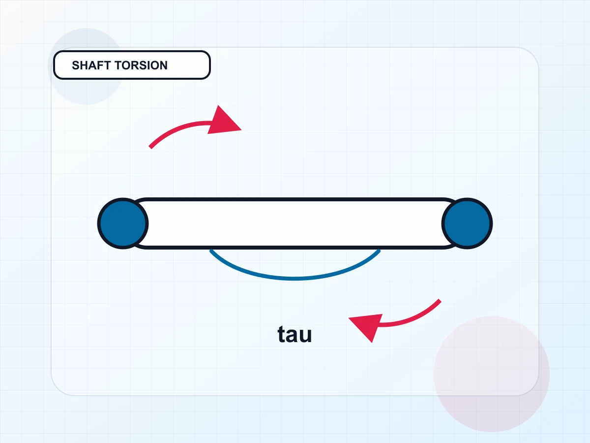
Torque alone does not size a shaft
The primary function of a shaft is torque transmission, but in practice a shaft simultaneously carries bending loads from gears, pulleys, and sprockets; axial thrust from helical gears or couplings; keyway stress concentrations; and cyclic fatigue from rotating-bending. The first sizing equation for a solid circular shaft is:
τ = 16T / (π d³)
where T is torque (N·mm), d is shaft diameter (mm), and τ is shear stress (MPa). Because diameter appears as a cube, a 10% diameter increase reduces shear stress by roughly 27%. The torsion formula is an essential first filter — but it is not a complete design.
Why angle of twist matters
A shaft can pass the strength check and still twist too much. The angle of twist θ (rad) over length L is:
θ = TL / (GJ)
where G is the shear modulus (for steel ≈ 80 GPa) and J = π d⁴ / 32 is the polar second moment of area. Excessive twist creates positioning error in indexing systems, unstable gear mesh contact, and phase lag in synchronised drives. In long, slender shafts the stiffness criterion often governs before yield stress does. Always verify both strength and stiffness.
Sizing steps
- Determine torque — identify peak torque (motor starting torque, shock loading) and continuous torque from the drive system.
- Calculate bending moments — from gear, pulley, and chain reaction forces at each load point along the shaft.
- Identify stress concentration zones — keyway, shoulder fillet, snap ring groove, spline runout, and thread undercut.
- Select allowable stresses — based on material yield strength, fatigue limit, surface finish Kₐ, size Kb, reliability Kc, and concentration factor Kt.
- Iterate diameter — using the combined von Mises equivalent stress for shafts carrying simultaneous bending and torsion.
- Check twist angle — compare θ against application-specific limits (typically 0.25°–1° per metre for general machinery).
Key, coupling, and gear hub effects
The weakest cross-section is rarely the plain shaft body. A parallel key slot removes material and introduces a sharp root radius. An improperly fitted gear hub creates fretting wear at the press-fit interface; a misaligned coupling adds a cyclic bending moment across every revolution. Good layout minimises the bending moment span — locate gears and pulleys close to bearings, and keep heavy components inboard.
Common design mistakes
- Using nominal motor torque only. Starting and peak torques can be 2–3× the rated value and must be checked.
- Sizing for stress, ignoring stiffness. An angle-of-twist check is mandatory in CNC axes, indexing tables, and gear trains.
- Neglecting stress concentration. A keyway Kt of 1.6–2.0 or a sharp shoulder fillet Kt > 2 significantly reduces the effective fatigue limit.
- Assuming high-strength steel is always better. Fatigue strength is sensitive to surface finish, stress concentration, corrosion, and residual stress — a stronger grade does not automatically deliver better fatigue life.
Application scenario
Consider a shaft with its gear located far from both bearings. The bending moment at the gear hub can dominate the stress calculation, even though the transmitted torque is modest. Changing the layout to move the gear inboard can reduce the required diameter — without changing any material property. This is why shaft sizing is a system-level task, not just a formula lookup.
What the torsion calculation leaves out
The torsion formula is a screening tool. A complete shaft design must also address:
- Combined bending and torsion (von Mises or ASME elliptic criterion for ductile materials)
- Fatigue life at notches and transitions under rotating bending
- Critical speed (lateral whirling) for long, high-speed shafts
- Bearing seat geometry, interference fit selection, and fretting risk
- Coupling type and alignment tolerance
- Manufacturing tolerances and surface treatment specified on the drawing
Once a diameter is fixed, the allowable stresses assumed in the calculation must be reproducible in production — specify heat treatment, surface roughness Ra, and inspection requirements on the drawing.
Related Torqyx calculator
Use the shaft torsion calculator to rapidly evaluate the torque–diameter–length relationship during conceptual sizing.
Shaft Torsion Calculator
CalculatorCalculate torsional shear stress and angle of twist from torque, shaft diameter, and length.
Related engineering guides
Technical references
- Shigley's Mechanical Engineering Design — Chapters on shaft design, stress concentrations, and fatigue.
- DIN 743 — Calculation of load capacity of shafts and axles.
- ISO 281 — Rolling bearings — Dynamic load ratings and rating life (for bearing seat sizing context).
Related posts
What is Gear Module? Sizing and Selection Guide
Master metric gear module sizing: understand the m = d/z relationship, standard module series (ISO 54 / DIN 780), bending strength, and undercut limits.
The Difference Between Torque and Power: An Engineering Perspective
Understand the fundamental relationship between torque and power, P = T x omega, and how to size electric motors and gear reducers correctly.
Ball Bearings vs. Roller Bearings: Sizing and Selection Criteria
Compare ball and roller bearings across radial load, axial thrust, rotational speed, misalignment tolerance, boundary lubrication, and ISO 281 L10 life.
Related calculators
Fillet Weld Sizing
Find required fillet size from load, weld length, and allowable stress.
Pulley Belt Length and Wrap Angle
Calculate open belt length, small pulley wrap angle, and tension allowance checks from pulley diameters and center distance.
Shaft Torsion
Compute torsional stress and twist angle from torque and shaft size.
Tensile Stress
Compute tensile stress from force and cross-section area.