
How to Calculate Hydraulic Cylinder Force and Speed
Calculate push and pull forces for hydraulic cylinders using pressure, bore diameter, and rod diameter. Account for mechanical efficiency and buckling safety.
Prepared and technically reviewed by: TORQYX Engineering Team · Methodology and team
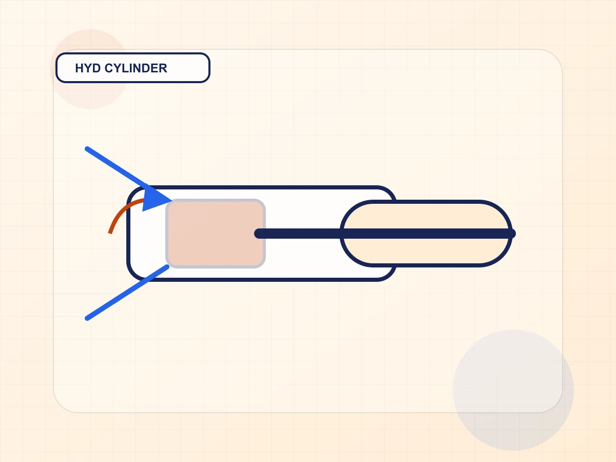
Fundamental relationship: force equals pressure times area
The fundamental governing equation for hydraulic cylinder thrust and pull force is derived from Pascal's law:
F_theoretical = p · A
where:
- F_theoretical is the ideal static output force (N)
- p is the working fluid pressure acting against the piston face (Pa or N/m²)
- A is the effective cross-sectional area exposed to pressurized hydraulic fluid (m²)
Because a conventional double-acting single-rod cylinder possesses an asymmetric interior geometry, the available working area differs significantly between extension (push) and retraction (pull) strokes:
-
Extension (Push Stroke) Area: The full circular bore cross-section is pressurized: A_bore = (π · D²) / 4 where D is the cylinder bore diameter (piston diameter). F_push = p · A_bore
-
Retraction (Pull Stroke) Annular Area: The piston rod occupies part of the rod-end chamber, reducing the net pressurized area to an annular ring: A_annulus = π · (D² - d²) / 4 where d is the piston rod diameter. F_pull = p · A_annulus
Consequently, at an identical system operating pressure, a single-rod hydraulic cylinder always generates more force on extension than on retraction. As rod diameter increases to resist buckling on long strokes, the annular area shrinks, amplifying this push/pull force disparity.
Unit conversions and real-world calculation engineering
In industrial fluid power, pressure is commonly specified in bar or MPa, cylinder dimensions in millimeters (mm), and output forces in kilonewtons (kN). Consistent SI unit handling is imperative:
- 1 bar = 0.1 MPa = 10⁵ Pa = 0.1 N/mm²
- 1 kN = 1,000 N
A convenient engineering rule of thumb: F (kN) = [p (bar) · A (mm²)] / 10,000
For example, a cylinder with an 80 mm bore operating at 160 bar:
- A_bore = π · (80)² / 4 ≈ 5,026.55 mm²
- F_push = (160 · 5026.55) / 10,000 ≈ 80.42 kN (theoretical thrust)
Real-world losses: mechanical and hydraulic efficiency
Theoretical force calculations represent static equilibrium without friction or fluid throttling. In practical machinery, available output force is reduced by:
- Piston and rod seal friction: Modern polyurethane U-cup or PTFE step seals exert preloaded contact pressure against honed tube walls and chromed rod surfaces. Seal friction consumes roughly 3–8% of available pressure.
- Backpressure in the return line: Fluid flowing out of the unpressurized chamber must pass through counterbalance valves, directional control valves, pipe friction, and return filter elements, creating resistive backpressure.
- Internal mechanical efficiency (η_mech): Industrial sizing typically applies an overall cylinder mechanical efficiency factor between η_mech = 0.85 and 0.95: F_actual = F_theoretical · η_mech
Designing an actuator with zero force margin invites sluggish cycle times, stalling under cold-oil startup conditions, and premature seal wear.
Actuator velocity and flow rate dynamics
Hydraulic pump displacement and flow rate (Q) govern the travel speed of the cylinder rod:
v = Q / A
where:
- v is rod linear velocity (m/s)
- Q is volumetric flow entering the active chamber (m³/s)
- A is the active chamber area (m²)
Because annular area is smaller than bore area (A_annulus < A_bore), the cylinder retracts faster than it extends for an identical pump delivery rate: v_retract = Q / A_annulus > v_extend = Q / A_bore
The volumetric ratio ϕ = A_bore / A_annulus is a critical parameter in reservoir and valve sizing. When a large bore cylinder retracts rapidly, oil exhausted from the cap end returns to the tank at flow rate Q_return = ϕ · Q_pump, which can overwhelm undersized directional valves or return line filters.
Long stroke buckling safety (Euler column formula)
For push-stroke applications where stroke length exceeds 6–10 times the bore diameter, cylinder selection cannot be based solely on thrust requirements. The extended piston rod acts as a slender structural column subjected to compressive axial loading.
According to Euler's buckling theory: F_critical = (π² · E · I) / L_effective²
where:
- E is Young's modulus of rod steel (≈ 210,000 MPa)
- I is the second moment of area of the solid rod: I = (π · d⁴) / 64
- L_effective is the effective buckling length, dictated by mounting boundary conditions (trunnion, clevis, spherical bearing, or rigid flange mounts as per ISO 6020)
A design safety factor S_buckling ≥ 2.5–3.5 must be verified under maximum peak relief valve pressure before committing to cylinder fabrication.
Related Torqyx calculator
Use the Torqyx Hydraulic Cylinder Force and Speed Calculator to rapidly compute bore thrust, rod pull, extension/retraction velocities, and fluid volume requirements.
Hydraulic Cylinder Calculator
CalculatorCompute push and pull forces, velocities, and flow rates from pressure, bore, and rod dimensions.
Related engineering guides
Technical references
- ISO 4413 — Hydraulic fluid power — General rules and safety requirements for systems and components.
- ISO 6020-1 — Fluid power cylinders — Mounting dimensions for single rod and double rod cylinders.
- ISO 6022 — Fluid power cylinders — Mounting dimensions for 160 bar and 250 bar series.
Related posts
What is Gear Module? Sizing and Selection Guide
Master metric gear module sizing: understand the m = d/z relationship, standard module series (ISO 54 / DIN 780), bending strength, and undercut limits.
Darcy-Weisbach Equation: Calculating Pipe Pressure Drop
Calculate frictional pressure loss in pipes using the Darcy-Weisbach formula, Reynolds number, relative roughness, and Colebrook-White friction factor.
The Difference Between Torque and Power: An Engineering Perspective
Understand the fundamental relationship between torque and power, P = T x omega, and how to size electric motors and gear reducers correctly.
Related calculators
Gear Force & Torque
Compute gear torque and transmitted forces.
Hydraulic Cylinder Force & Speed
Compute extend/retract force and speed from pressure and flow.
Pulley Belt Length and Wrap Angle
Calculate open belt length, small pulley wrap angle, and tension allowance checks from pulley diameters and center distance.
Spring Force Chart
Generate an F-x chart from spring constant and displacement.