
Skip to content

Standards

Metric threads: practical standards notes

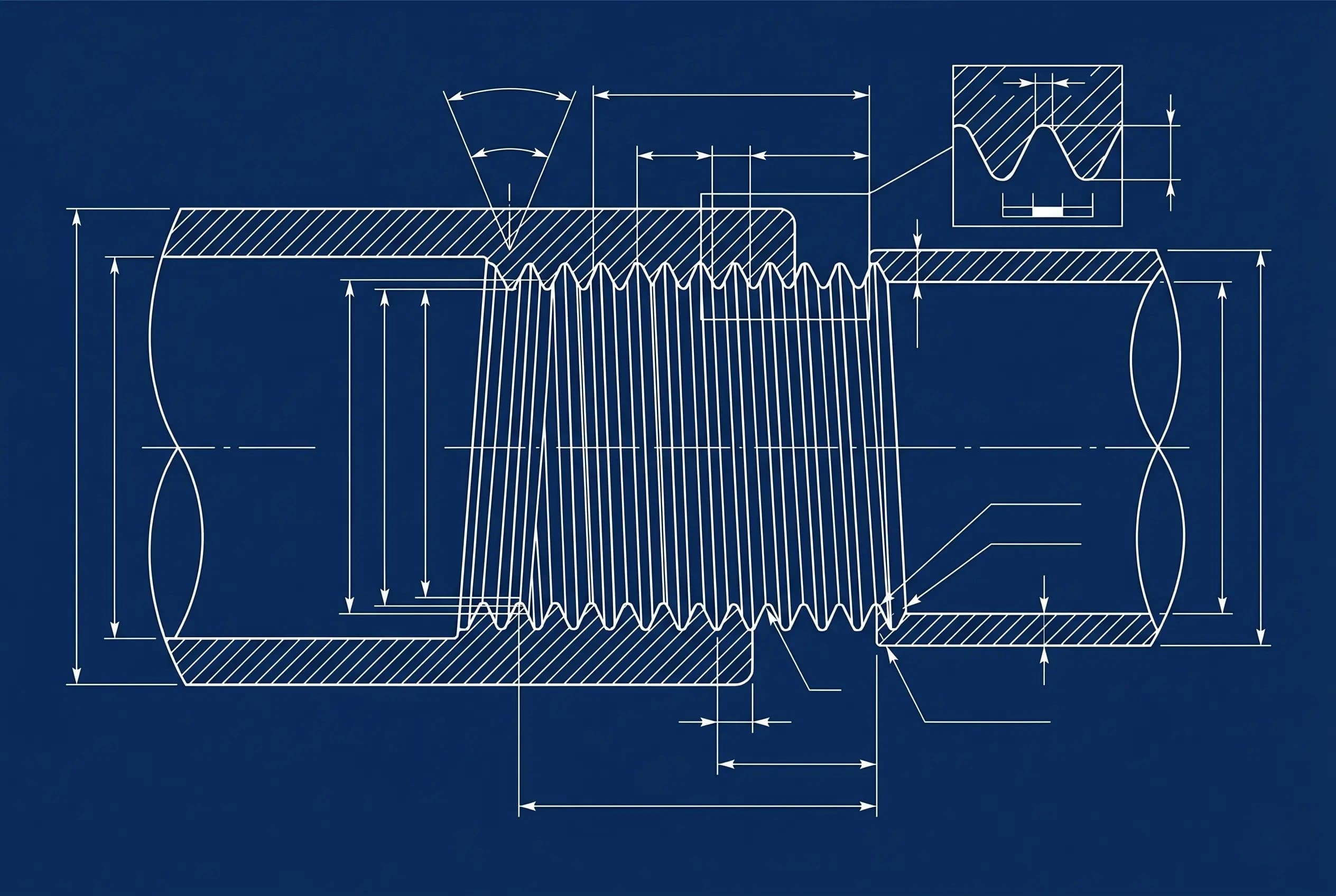
A practical view that separates coarse/default pitch, fine pitch, tap drill diameter, and clearance hole diameter.

Metric threads engineering reference

Coarse (standard pitch)

Default when pitch is omitted. For example, M8 by itself means M8x1.25.

  • For M8 coarse/default, the common tap drill is 6.8 mm.
  • More robust against dirt and handling damage.
  • Use locking features in vibration-heavy applications.

Fine pitch

Uses a smaller pitch at the same nominal diameter, so the tap drill diameter differs from the coarse series.

  • The pitch must be called out, such as M8x1; typical tap drill for M8x1 is 7.0 mm.
  • Works well in thin-wall sections.
  • Improves clamp adjustment sensitivity.

Common pitch and tap drill snapshot

Practical starting values for coarse/default and fine pitch. Tap drill means the pre-hole before threading.

SizeCoarse P (mm)Coarse tap drillFine P -> drill
M30.52.5 mm0.35 -> 2.65 mm
M40.73.3 mm0.5 -> 3.5 mm
M50.84.2 mm0.5 -> 4.5 mm
M615 mm0.75 -> 5.2 mm
M81.256.8 mm1 -> 7 mm
M101.58.5 mm1.25 -> 8.8 mm / 1 -> 9 mm
M121.7510.2 mm1.5 -> 10.5 mm / 1.25 -> 10.8 mm
M16214 mm1.5 -> 14.5 mm
M202.517.5 mm2 -> 18 mm / 1.5 -> 18.5 mm
M24321 mm2 -> 22 mm

Mini Tool

Tap drill calculator

Shows the common workshop drill first; the calculated value below changes with selected thread engagement.

Tap drill diameter

Common workshop value

6.8 mm

Selected thread
M8x1.25 (Coarse / default)
Calculated from engagement
6.8 mm

This is the pre-hole for tapping; bolt clearance holes are separate in the table below.

Starting point for hard materials: 6.95 mm

Copy-ready callout

M8x1.25 - 6H/6g

Formula note

D_tap ≈ D_nominal - P x (engagement/77)

The table value is a practical standard starting point; the calculated value helps trade thread height against tap load.

Example: M8 = M8x1.25 coarse/default with a 6.8 mm tap drill; M8x1 fine pitch typically uses a 7.0 mm tap drill.

Clearance hole quick table

Close / normal / loose diameters are for free bolt passage; do not mix them with tap drills.

SizeCloseNormalLoose
M33.23.43.6
M44.34.54.8
M55.35.55.8
M66.46.67
M88.4910
M1010.51112
M121313.514.5
M16171819
M20212224

Thread engagement length (rule of thumb)

Good for early design loops. Validate by standard/tolerance and critical-load checks.

MaterialGuidelineNote
Steel base material1.0 x DTypical starting point for general machine design.
Cast iron (EN-GJL / EN-GJS)1.2 x DSlightly longer engagement helps brittle base materials.
Aluminum alloy1.5 x DLonger thread reduces stripping risk in softer alloys.
Brass / Bronze1.2-1.5 x DUse upper range for frequent assembly/disassembly.
Plastics (PA6, POM, etc.)2.0 x D + insertPrefer metal threaded inserts for durability.

Fit and tolerance notes

  • Common combination: internal 6H with external 6g.
  • Add lead-in chamfers where threads are near locating features.
  • In corrosive environments, use stainless fasteners with suitable anti-seize.

References

  • ISO 68-1: Basic profile for ISO metric screw threads
  • ISO 261: ISO general purpose metric screw threads - General plan
  • ISO 965-1: Tolerances for metric screw threads
  • Machinery's Handbook, latest edition (threading chapters)